
A battery and an inverter that “both speak CAN” can still fail to talk to each other. CAN is a bus, not a language: it moves frames from one device to another, but the two ends must agree on what each frame carries, how fast the bus runs, and which wire is which. This page explains what actually rides the CAN bus between a LiFePO4 battery management system (BMS) and an energy storage inverter — the frame map, the choice between CAN and RS485, the wiring rules that decide whether the link is stable, and the checks that find the fault when it will not come up.
The physical layer is simple: two wires, CAN H and CAN L, carrying a differential signal, with a 120 Ω terminator at each physical end of the bus. The BMS does the talking: it broadcasts its frame set once a second at 500 kbps — the rate most stationary storage inverters use — and the inverter answers with a short heartbeat frame. The inverter does not poll for data; it listens, reads the charge and discharge limits, the state of charge and the alarm flags, and follows them. That broadcast habit is what makes CAN different from RS485 Modbus, and it is also why a single wrong setting — baud rate, termination, or a frame the inverter does not recognize — can silence the whole link. LJY Energy is a LiFePO4 battery supplier and OEM/ODM coordinator in Shenzhen; we are not a factory. The BMS communication profile for your inverter is confirmed in writing for your project, against the inverter model and firmware you will actually ship.
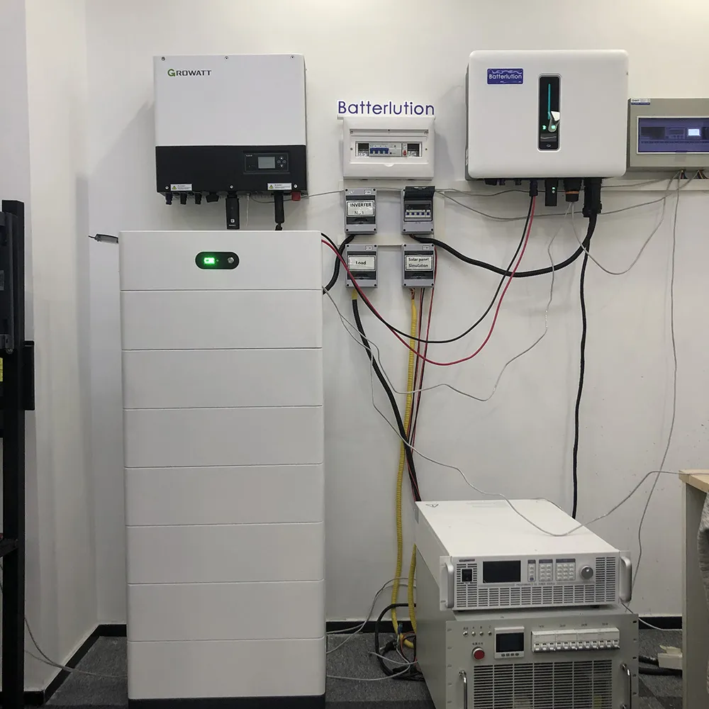

The BMS CAN link at a glance
| Bit rate | 500 kbps |
| Broadcast cycle in seconds | 1 |
| Termination at each end | 120 Ω |
| Maximum bus length in meters | 100 |
| Maximum data bytes per frame | 8 |
| CAN IDs in the BMS frame map | 6 |
| Standard-frame identifier in bits | 11 |
| Signal wires in the bus | 2 |
For which profile to select on each inverter brand, see the closed-loop inverter communication guide.
Worked example: one second of bus traffic
Take a 51.2 V pack talking to its inverter at 500 kbps. Every 1 second the BMS sends 6 frames. 0x351 carries the charge voltage limit and the charge and discharge current limits — the three numbers the inverter must obey. 0x355 carries the state of charge and the state of health. 0x356 carries the pack voltage, the current and the average cell temperature. 0x359 carries the protection and alarm flags. 0x35C carries the charge request flags. 0x35E carries the manufacturer name. The values are scaled: voltages in 0.1 V steps on 0x351 and 0.01 V steps on 0x356, currents in 0.1 A steps, temperature in 0.1 °C steps, and state of charge and state of health in whole percent. Each frame holds up to 8 data bytes, the identifier is 11 bits, and the whole set repeats every 1 second — so a CAN logger on the bus shows the same 6 identifiers, second after second, with the values moving as the pack charges or discharges. The inverter answers with a short heartbeat frame, 0x305, once a second. The bus itself is 2 wires, CAN H and CAN L, with a 120 Ω terminator at each physical end, and at 500 kbps it reaches about 100 meters. If the logger shows the 6 identifiers but the inverter still reports no battery, the frames are fine and the fault is on the inverter side — the profile, the port, or the firmware. If the logger shows nothing at all, the fault is on the bus — the cable, the termination, or the baud rate.
What to check when the link will not come up
- The cable and the pinout first — CAN H and CAN L swapped, or a straight network cable with the wrong pin assignment, is the most common cause of a silent bus; compare the battery port pinout drawing with the inverter manual before anything else
- The termination — with the power off, measure across CAN H and CAN L: about 60 Ω means two 120 Ω terminators are in place, one at each end; about 120 Ω means one is missing, and a much lower reading means an extra terminator is fitted somewhere it should not be
- The baud rate — both ends must run the same rate; a battery set to 500 kbps and an inverter listening at 250 kbps will never see each other, and the symptom is a bus that looks dead on both sides
- The identifiers and the firmware — confirm the BMS sends the frame set the inverter expects, that no two packs share an address on a parallel bus, and that the inverter firmware is the version the pairing was tested against; a firmware update can change which frames the inverter reads
Discuss BMS CAN communication for your project
CAN or RS485? The answer depends on what the other end expects. CAN suits the battery-to-inverter link: it broadcasts, so the inverter always has fresh limits without asking; it arbitrates, so several packs can share one bus without a master polling each one; and it is the link most hybrid inverters are built around. RS485 with Modbus suits the monitoring path: it reaches further — over a kilometre where CAN at 500 kbps reaches about 100 meters — and it fits the register-map habit of monitoring systems, but it needs a master to poll, and only one device talks at a time. Where an inverter offers both, CAN is usually the closed-loop choice and RS485 the monitoring choice; where it offers one, that decides it. The wiring rules are short and unforgiving: a line topology, not a star; a 120 Ω terminator at each physical end and nowhere else; short stubs; twisted-pair cable, shielded where the run passes inverters or motors; and the two ends agreeing on the baud rate before the cable is even pulled. Length trades against speed: about 40 meters at 1 Mbps, 100 meters at 500 kbps, 250 meters at 250 kbps, 500 meters at 125 kbps. One more trap: the same protocol name can hide different frame sets. The widely used inverter CAN dialect has more than one revision — the newer revision sends alarms on 0x35A and battery information on 0x35F instead of 0x359 and 0x35C — so always confirm which revision the BMS speaks and which revision the inverter expects, in writing, for the exact models and firmware in the order. For which profile to select on each inverter brand, see the closed-loop inverter communication guide; for the UPS side of the same question, see the rack battery UPS communication protocols page; for J1939 and CANopen in vehicle and equipment batteries, see the BMS CAN guide for OEMs; and for the pass-or-fail checks before you sign, see the closed-loop acceptance test. Send us the inverter model and firmware and the battery profile you plan to select, and LJY Energy will confirm the BMS communication setup in writing. We coordinate OEM/ODM battery supply from Shenzhen; we are not a factory.

Ask about BMS CAN communication for your inverter · WhatsApp +86 159 8945 0735